

Learn about the GrabCAD Platform
Get to know GrabCAD as an open software platform for Additive Manufacturing
Visit our new homepage


Project from 3D constructor - https://dubina.biz
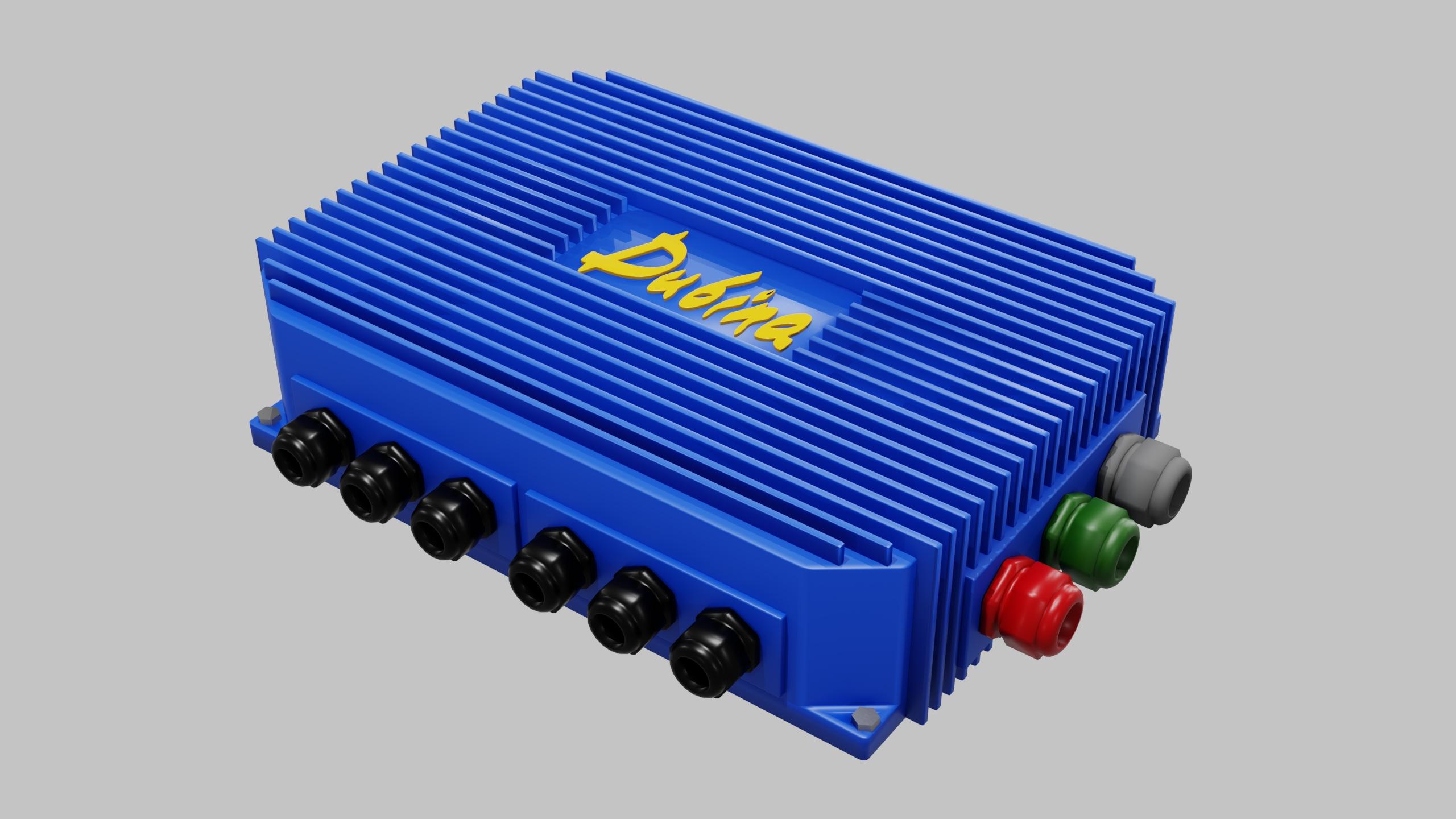
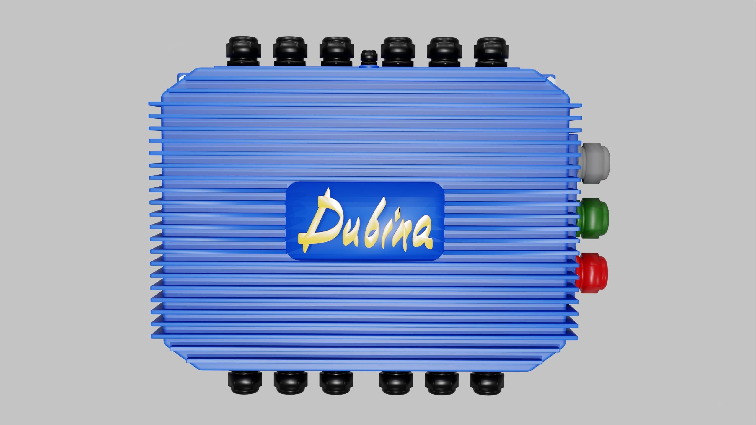
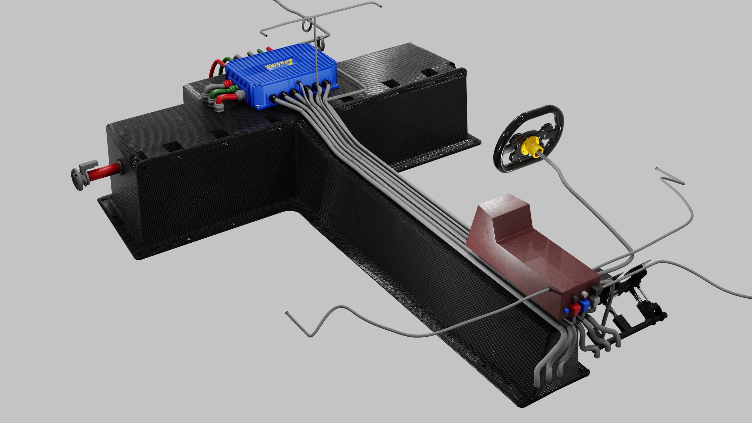
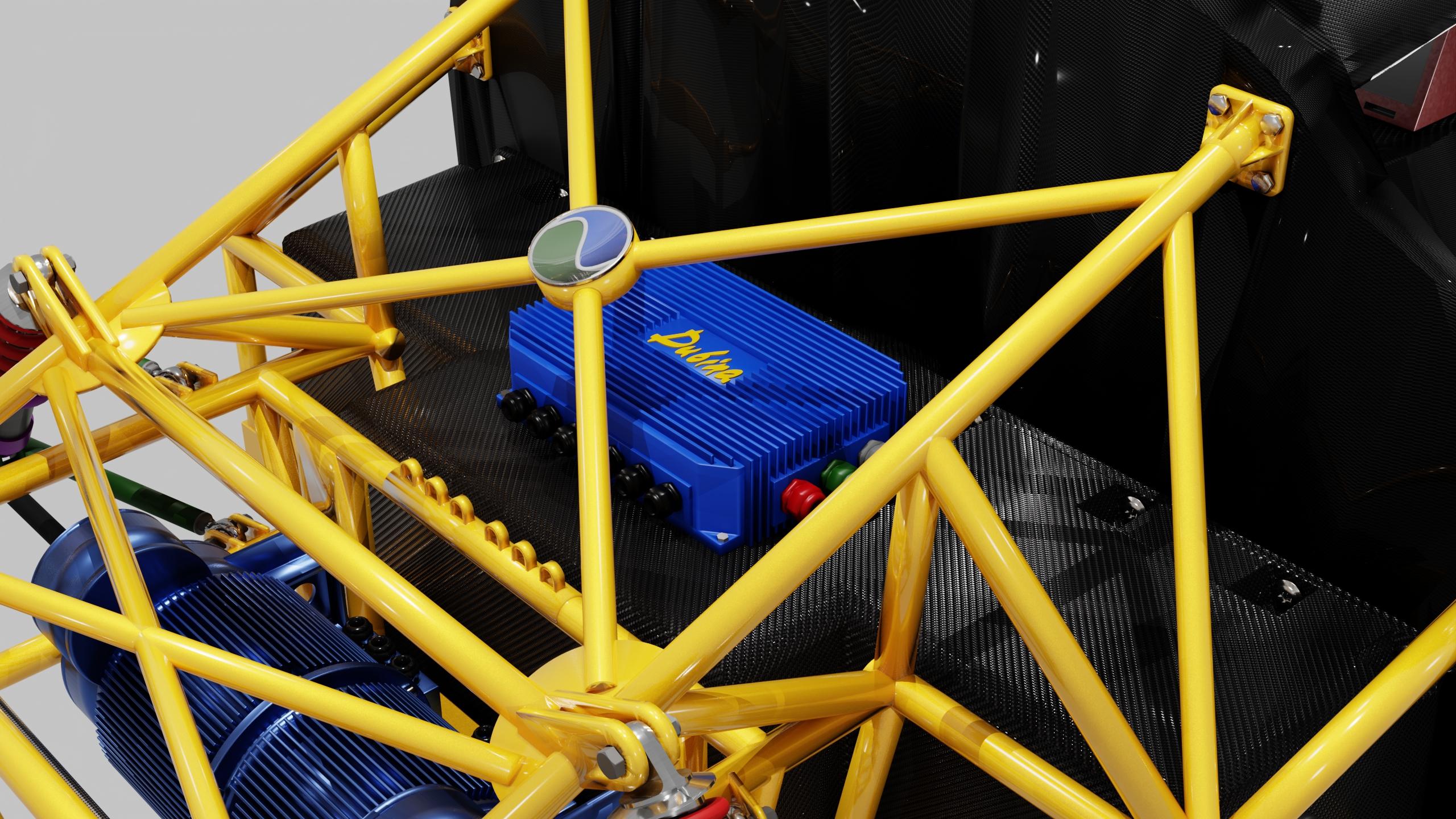
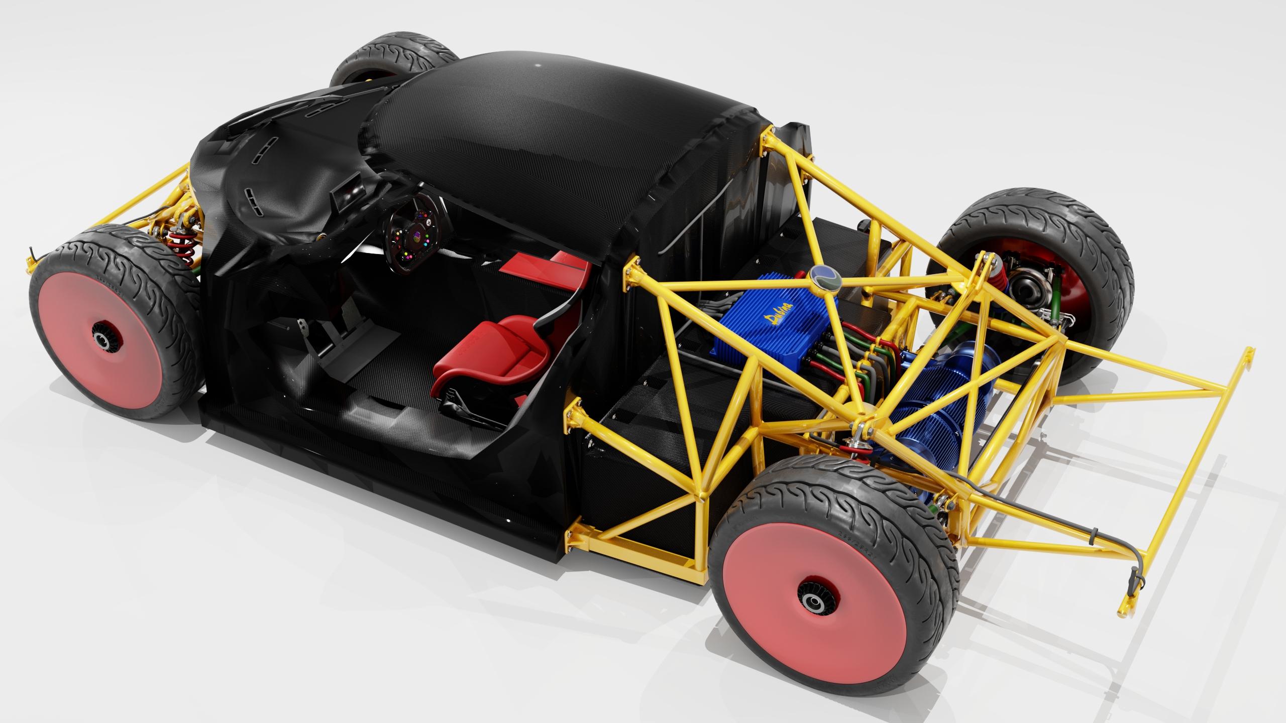
The car uses brushless motors with reverse. To control them, a speed controller is used. It is involved in starting, speed control, braking and reversing, and also carries out the work of control technologies and systems. The controller uses semiconductor devices, it has no moving parts. Energy from semiconductor components comes to the motor in pulses, and all adjustments are made by changing the pulse duration. Semiconductor switching elements have high power, fast response, high reliability, small size, weight. Solid-state equipment in the speed controller is divided into two main parts. The first, power, includes silicon-controlled rectifiers: thyristors, triacs, locking devices, power transistors and diodes. The second, logical, includes integrated circuits and microprocessors. Power electronic equipment is divided into four main categories: rectifiers, inverters, interrupters and cycloconverters. A cycloconverter converts the current frequency without changing the output voltage. Direct current comes from the battery. Direct current is fed to the inverter circuit, which creates a three-phase alternating current with an output voltage. The frequency converter for a three-phase electric motor is a device that regulates the frequency, voltage of electricity supplied to the electric motor. It allows you to change the speed of the motor, providing precise control, changes the speed of the motor by changing the alternating current in each phase using a pulse-width modulation device, thereby changing the effective output signals that control the three-phase motor from a typical alternating current wave to a new pulse-width modulation wave. The operating frequency range of the speed controller is from 10 Hz to 400 Hz. The controller operates with high voltage, so it has an optocoupler built in. This is a galvanic isolation of the power circuits from the receiver circuits of the control system. This is done so that powerful impulse interference from the power section of the controller and the motor does not get to the highly sensitive input circuits of the control unit. Therefore, the control unit uses a separate power supply. The speed controller supplies high voltage to the motor winding. The conductor temperature is determined by the formula: Q = I ^ 2 R t. This formula describes the process of converting electrical energy into heat. Therefore, the speed controller changes the current characteristics, but not the output voltage. If the voltage on any phase is less than 120 V, the engine will generate excess heat and quickly burn out. The speed controller not only quickly spins the engine at the start, but also quickly slows it down. The controller performs "soft" braking, the windings are not closed immediately, but in small pulses. This reduces the heating of the controller and extends the life of the electric motor collector. The controller performs reverse, it changes the direction of rotation of the electric motor, supplying voltage to it in reverse polarity. The controller has a function of turning off the electric motor, it stops the engine when the voltage in the battery drops below a certain level. After turning off the engine, the battery still has some energy for the operation of other systems: the speed controller, the control unit. Instead of using one common speed controller for the motors, each electric motor has its own speed controller. The car has four electric motors and four speed controllers. Using a separate controller for each electric motor reduces energy losses and improves controller performance. Separating the regulators allows the thermal load to be distributed more evenly, which reduces the risk of overheating and can increase the life of components. The speed controller uses efficient electronic components that work together to create a reliable and safe speed controller capable of controlling a 75 kW electric motor at 400 V and 200 A. To control a 75 kW electric motor with an operating voltage of 400 V and a current of 200 A, powerful MOSFETs with appropriate characteristics are used. The MOSFET in the speed controller has a maximum drain-source voltage (V_DS) well above the operating voltage to provide voltage headroom. For 400 V operating voltage, a MOSFET with a V_DS of about 600 V or higher is used. The MOSFET in the speed controller has a maximum drain current (I_D) of 250-300 A to ensure reliability and resistance to peak loads. The MOSFET in the speed controller has a minimum on-resistance (R_DS(on)) to reduce heat generation and improve efficiency. This value is less than 10 mOhm. The MOSFET in the speed controller has a transition temperature (T_j) high enough up to 150-175°C to withstand thermal loads. The speed controller uses a MOSFET: Infineon Technologies IPW60R070C6. V_DS = 600 V; I_D = 200 A (at 25°C); R_DS(on) = 0.07 Ohm. The speed controller can also use a Wolfspeed C3M0075120K MOSFET with V_DS = 1200 V; R_DS(on) = 75 mOhm. SiC (silicon carbide) provides high efficiency and heat management at high power and voltage. The design of the regulator took into account the control circuit, cooling system, drivers for controlling MOSFETs and protection against overvoltage and overload. With low on-resistance (RDS(on)), the MOSFET minimizes energy loss, making it particularly effective in high-current applications such as 75 kW electric motors. The speed controller uses: power components, logic components, protection elements, capacitors. The speed controller uses a power component, the Semikron SKKT 330/16E thyristor. It is a controlled rectifier for converting direct current into regulated alternating current. Maximum current = 330 A. Maximum voltage = 1600 V. The speed controller uses a power component IGBT (insulated gate bipolar transistor) Infineon IGBT FF200R12KT4. It generates a three-phase alternating current with a controlled frequency. The rated current is 200 A. The maximum voltage is 1200 V. The speed controller uses a power diode IXYS DSEP60-12A. It provides reverse conductivity in the rectifier and inverter circuits. Maximum current 200 A. Maximum voltage 1200 V. The speed controller uses a logic component microcontroller STM32F407 (STMicroelectronics). It controls the pulse-width modulation (PWM), sensor signal processing and control of power components. Clock frequency up to 168 MHz. RAM 192 KB. The speed controller uses a logic component optocoupler Broadcom ACPL-331J. It performs galvanic isolation between high-voltage and low-voltage circuits. Isolation voltage up to 3750 V. Transfer rate up to 10 Mbit/s. The speed controller uses a protection element, the EPCOS S20K275 varistor. It protects against voltage surges and short circuits. The response voltage is 275 V. The speed controller uses a Bussmann FWP-200A fuse protection element. It quickly disconnects circuits during overloads. Nominal current 200 A. Nominal voltage 500 V. The speed controller uses a power capacitor EPCOS B32774. It smooths out pulsations and maintains a stable voltage in the inverter circuit. Capacity 100 μF. Voltage up to 600 V. The capacitance of a capacitor Q is determined by the formula: C = Q ⋅ U; C — capacitance, F; Q — charge, C; U — voltage, V. The energy stored by the capacitor W is determined by the formula: W = C ⋅ U^2 / 2; W — energy, J; C — capacitance, F; U — voltage, V. The current through the capacitor when the voltage I changes is determined by the formula: I = C ⋅ (dU/dt); I — current, A; C — capacitor capacitance, F; dU/dt — rate of voltage change, V/s. The impedance of the capacitor Z is determined by the formula: Z= 1 / (2πfC); Z — impedance, Ohm; f — frequency, Hz; C — capacitor capacitance, F. The speed controller uses a Vishay MKP1848 blocking capacitor. It blocks high-frequency interference. Capacity 1 μF. Voltage up to 1200 V. The speed controller uses LEM HASS 200-S current sensors. They measure the current in real time for engine control. Current range is ±200 A. The speed controller uses Vishay WSMS2906 shunts. They are for precise current measurement. Current up to 300 A. Resistance 0.001 Ohm. The speed controller uses thermistors to monitor the temperature of the power components. The speed controller uses heat-conducting pads to improve heat dissipation from IGBT and thyristors to radiators. For better cooling, the speed controllers are located under the engine in the place of the ventilation hole.
Please do not open any links and do not make calls (including WhatsApp) to any numbers from messages sent by accounts such as Grabcad Verification, etc. - these are phishing ones. Please do not make any payments. Our security team is currently working on a solution.