

Learn about the GrabCAD Platform
Get to know GrabCAD as an open software platform for Additive Manufacturing
Visit our new homepage


Project from 3D constructor - https://dubina.biz
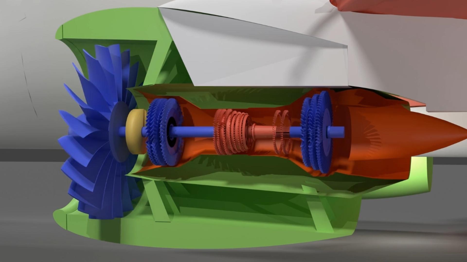
The aircraft has a twin-shaft, dual-circuit turbofan engine with a geared fan drive. Engine thrust is 110 kN (this is approximately 11 tons of thrust). Engine length is 3.5 m. Dry engine weight is 2800 kg. The low-pressure rotor has a 2-meter diameter fan consisting of 20 wide carbon fiber blades with titanium fairings. The fan generates 80% of the engine's total thrust. The engine's bypass ratio is 12:1. This means that only one-twelfth of the air from the fan enters the inner circuit. First, the air flow in the internal circuit enters the 3-stage low-pressure compressor located on the low-pressure shaft. One stage of the compressor consists of two parts. Rotor blades, movable - are fixed on the shaft, rotate with it. Stator blades, fixed - are fixed on the engine body, stand still. Passing through the stationary stator guide blades located on the engine body, they correct the angle of attack of the flow. Then the flow enters the rotor blades, which accelerate it. After leaving the rotor, the stator blades of the next stage go again, and so on. The function of the stator blades is to convert the air velocity into pressure. They straighten the flow so that it enters the following rotor blades correctly. In this way, they increase the efficiency of the engine by reducing turbulence. Rotor blades accelerate the air flow, giving it speed. When the rotor blades spin the air, the flow accelerates and acquires high speed, but the pressure is not yet high. Stator blades slow down this accelerated flow and convert its kinetic energy into increased pressure. If you let the air flow further without the stator blades, the next rotor will not work efficiently. After the low-pressure compressor, the air enters the 8-stage high-pressure compressor located on the high-pressure shaft. The high-pressure compressor compresses the air 50 times, heating it up to 300 °C, and the air enters the annular combustion chamber through small injector channels. The mixture of air and fuel ignites uniformly in the combustion chamber. It is because of the pressure that the fuel burns well in the combustion chamber. The combustion chamber maintains the correct direction and combustion. The combustion chamber uses ring-type injectors that spray fuel. The injectors are two-phase air-jet. The injector has channels for supplying fuel and air. The injector mixes the fuel with air, creating a finely dispersed fuel-air cloud for stable and complete combustion. Due to the air, the fuel is broken up into small droplets. The injectors operate at high temperatures and pressures. High spray uniformity prevents local overheating of the chamber walls. The smaller the droplets, the faster and more completely the fuel burns. Good atomization prevents the formation of soot, minimizing carbon monoxide and nitrogen emissions. The injectors operate in a wide range of modes from starting to cruising flight. The engine has 20 injectors, evenly distributed along the combustion chamber ring. They are resistant to surge and flame attenuation. Ignition is performed by electric spark plugs. There are two of them in the chamber, in case one fails. Electric spark plugs in the engine serve for the initial ignition of the fuel-air mixture in the combustion chamber, when starting the engine or during repeated ignition in flight. Electric spark plugs receive a high-voltage electrical impulse from the engine ignition system. This impulse causes a spark between the electrodes of the spark plug. The spark ignites the fuel-air mixture, which then maintains combustion due to the constant combustion process in the chamber. After the combustion chamber, the gas flow passes a high-pressure turbine made of a nickel-based heat-resistant alloy located on the high-pressure shaft, which drives the high-pressure compressor. After the high-pressure turbine, the gas enters the low-pressure turbine located on the low-pressure shaft and driving the low-pressure compressor and fan through a planetary gearbox. The engine's gearbox optimizes fan and turbine operation. The gearbox optimizes fan and turbine performance. The turbine is highly efficient at high speeds. The fan operates more efficiently at low speeds. The gearbox has a 3:1 gear ratio. The fan speed is 3,000 rpm, and the turbine speed is 9,000 rpm. The gearbox is designed for high torque with minimal energy loss. It allows for a fan diameter of up to 2 meters while maintaining the engine's compact size. The fan blades rotate at approximately Mach 1. The large, slow-speed fan reduces noise levels by almost 75%, as perceived by humans. Fan noise levels are 50% lower than those of gearless engines. The larger fan draws more air through the outer contour, reducing specific fuel consumption and increasing thrust during takeoff. This optimization reduces fuel consumption by 20%. Fewer turbine stages are required because the turbine spins faster and transfers energy more efficiently. At the end of the inner circuit, the hot gas exits through the gas generator nozzle. At the end of the outer circuit, cold air exits through the fan nozzle. The entire engine is housed in a carbon fiber casing. The engine uses fuel obtained from recycled waste, including plastic bags, paper packaging, and plant residues. The waste is processed and separated by density, then liquid hydrocarbons are synthesized from the resulting mass using pyrolysis, which heats the waste in the absence of oxygen. Pyrolysis converts plastic and organic matter into liquid hydrocarbons. The processes at a waste processing plant are similar to those performed with crude oil in an oil refinery. The resulting engine fuel is similar to aviation kerosene.
Please do not open any links and do not make calls (including WhatsApp) to any numbers from messages sent by accounts such as Grabcad Verification, etc. - these are phishing ones. Please do not make any payments. Our security team is currently working on a solution.