Learn about the GrabCAD Platform
Get to know GrabCAD as an open software platform for Additive Manufacturing
Visit our new homepage


Project from 3D constructor - https://dubina.biz
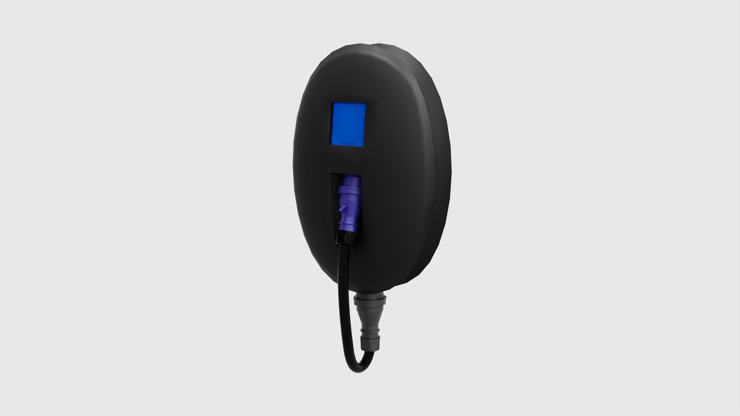
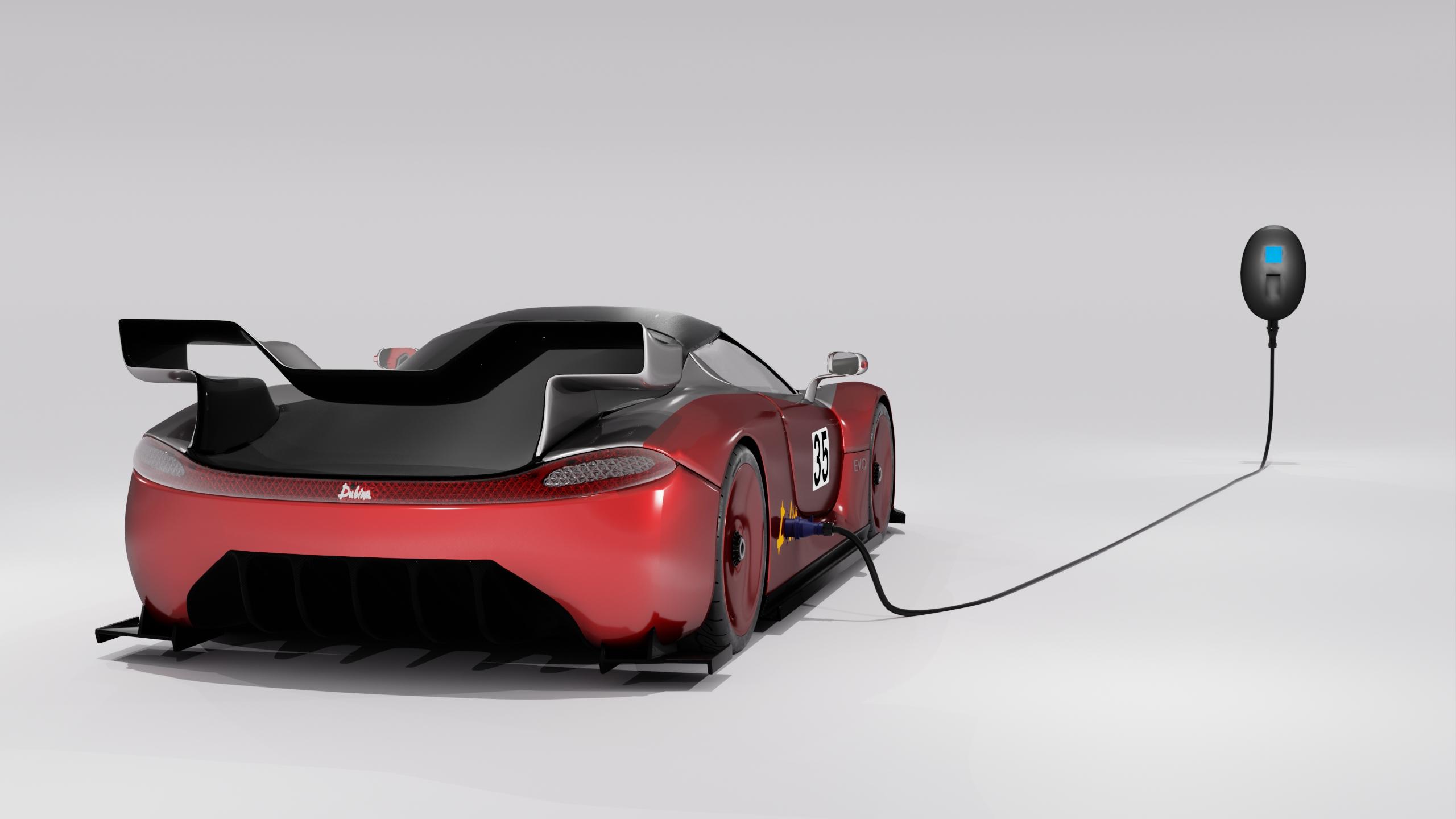
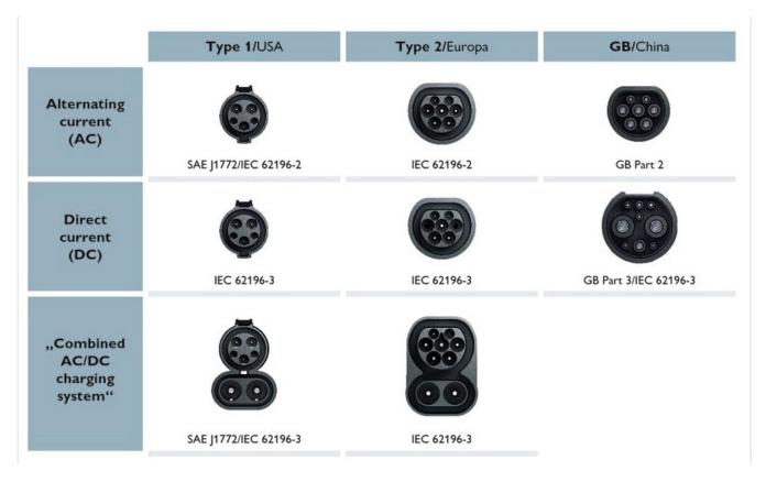
The car battery is charged by a charger. The charging station is connected to the city network of alternating three-phase current with a voltage of U = 220 V and a frequency of current in the network f = 50 Hz. With the help of the charger, alternating current is converted into direct current, which is necessary for charging the battery. The converter from alternating current to direct current is built into the charger, not into the car, in order to avoid size and weight restrictions. The charger is mounted on the wall. At a current of I = 50 A, the charging station produces 11 kW of power. The maximum power of the charging station is 25 kW. It works with a voltage of 120 to 400 V and a current of up to 100 A. At a voltage of 220 V and a current of 30 A, the charging power is 6.6 kW. A battery with a capacity of 90 kW will be charged in 13.5 hours. The charger is made of durable plastic. The case has a display showing information about the current, voltage, and charging time. The case is oval-shaped with a recess for winding the cable. The size of the charging station is 600x350x250 mm. The cable is wound and secured with a plug into the socket on the case. Socket type IEC 62196-3 type 2. The connector is round with a flat top edge. The diameter of the connector is 70 millimeters, the height is 63 millimeters. This is a 7-pin connector consisting of 1 ground, 3 positive, 1 negative, 2 signal. The special feature of the connector is the ability to use a single-phase and three-phase network, with a maximum voltage of 480 V and a current of 50 A. The connector allows the use of charging stations with Mode 2, Mode 3 operating modes. In January 2013, the European Commission selected the IEC 62196 Type 2 connector as the official charging connector in the European Union. Since then, it has been adopted as a recommended connector in some countries outside Europe, including New Zealand. There are many types of charging connectors. Depending on the region and standards, connectors of the Mennekes type (for Europe), SAE J1772 (in North America), or others may be used, and a connector for direct current (DC) may also be present. For standardization and ease of use, it is desirable to use one type of connector on all vehicles. The plug is connected to the cable. In order for the cable to be elastic and to be able to wrap it, hanging it on the charging station, it is made multi-core. The cable for the charging station consists of five conductive cores, each core is 10 mm2. The cable length is 6 m. The outer part of the wire is equipped with protective insulation that can withstand mechanical damage, heating and moisture. The charger uses silicon rectifiers. Their advantage is that during the battery charging process, the charging current can be adjusted within a wide range, and since a voltmeter, ammeter and fuses are mounted on the rectifier itself, no separate charging boards are required. In this case, charging is carried out according to the rectifier-battery scheme. Therefore, the charger has high efficiency, increased reliability, good thermal characteristics, small size and cost. Silicon carbide components play an important role in these parameters. They are combined with existing silicon MOSFET and silicon carbide switches to achieve maximum efficiency with a relatively small number of components. Air-cooled modules with a power of 30 kW and above, which use appropriate gate drivers and control electronics, meet the requirements of international charging standards.
Please do not open any links and do not make calls (including WhatsApp) to any numbers from messages sent by accounts such as Grabcad Verification, etc. - these are phishing ones. Please do not make any payments. Our security team is currently working on a solution.